ESP32 WiFi Sniffer[Part 1]
Ingredients
- ESP32
- OLED Screen SSD1306
- Jumper Wires
- Breadboard
- Arduino IDE setup for ESP32
Introduction
For as long as I can remember, I’ve been really interested in low level programming. I love messing with hardware and, something about C and C++ have always fascinated me. I’ve always looked up to the C wizards, with such a deep understanding of technology that they can accomplish things most people couldn’t dream of. Wanting to gain some experience with hardware and low level programming, I ordered a few ESP32 and some OLED screens. Once they arrived the first order of business was testing them to see if the WiFi adapter built in supported promiscuous mode.
Promiscuous Mode
I’ll start assuming you have your ESP32 development environment setup already. There are a ton of articles and tutorials out there explaining getting this setup on Linux, Mac and Windows. Once we are done testing for promiscuous mode we’ll know what our limitations may be (at least out of the box). Then we can decide what we’re going to build. We’ll also go over setting up and troubleshooting the SSD1306 OLED Screen. Before we get into testing for promiscuous mode on our WiFi adapter, lets talk for a minute about what promiscuous mode is. By default, most wired and wireless network cards will drop any frame with a destination address that it does not know. In other words, they will ignore all traffic that is not specifically for that interface. Though this is the normal behavior for a network card, it’s not the only way. When we enable promiscuous mode for a network card, it will stop ignoring frames not addressed to it and will start to capture all frames. This functionality can be very handy when debugging network issue, but it can also be used maliciously by attackers. Not only does this allow for man in the middle attacks, but we can also perform things like deauth attacks in order to disrupt wireless networking. Now that we have a very high level idea of what promiscuous mode is, lets check if it is enabled on our ESP32.
#include "esp_wifi.h"
#include <vector>
#include <SPI.h>

using namespace std;

#define maxCh 11

int curChannel = 1;
int currentPage = 1;
long lastPageChange = 0;
vector<String> macArray;

const wifi_promiscuous_filter_t filt = {
    .filter_mask=WIFI_PROMIS_FILTER_MASK_MGMT|WIFI_PROMIS_FILTER_MASK_DATA
};

typedef struct {
    uint8_t mac[6];
} __attribute__((packed)) MacAddr;

typedef struct {
  int16_t fctl;
  int16_t duration;
  MacAddr da;
  MacAddr sa;
  MacAddr bssid;
  int16_t seqctl;
  unsigned char payload[];
} __attribute__((packed)) WifiMgmtHdr;

void sniffer(void* buf, wifi_promiscuous_pkt_type_t type) {
    wifi_promiscuous_pkt_t *p = (wifi_promiscuous_pkt_t*)buf;
    WifiMgmtHdr *wh = (WifiMgmtHdr*)p->payload;

    MacAddr mac_add = (MacAddr)wh->da;
    String destinationMac;
    for (int i = 0; i < sizeof(mac_add.mac); i++) {
        String macDigit = String(mac_add.mac[i], HEX);
        if (macDigit.length() == 1) {
            macDigit = "0" + macDigit;
        }

        destinationMac += macDigit;
        if (i != sizeof(mac_add.mac) - 1) {
          destinationMac += ":";
        }
    }

    destinationMac.toUpperCase();

    // Prevent duplicates
    for (int i = 0; i < macArray.size(); i++) {
        if (destinationMac == macArray[i]) {
            return;
        }
    }

    macArray.push_back(destinationMac);
    Serial.println(destinationMac);
}

void setWifiPromiscuousMode() {
    wifi_init_config_t cfg = WIFI_INIT_CONFIG_DEFAULT();
    esp_wifi_init(&cfg);
    esp_wifi_set_storage(WIFI_STORAGE_RAM);
    esp_wifi_set_mode(WIFI_MODE_NULL);
    esp_wifi_start();
    esp_wifi_set_promiscuous(true);
    esp_wifi_set_promiscuous_filter(&filt);
    esp_wifi_set_promiscuous_rx_cb(&sniffer);
    esp_wifi_set_channel(curChannel, WIFI_SECOND_CHAN_NONE);
}

void setup() {
    Serial.begin(115200);

    setWifiPromiscuousMode();
}

void changeWifiChannel() {
    if(curChannel > maxCh){
        curChannel = 1;
    }

    esp_wifi_set_channel(curChannel, WIFI_SECOND_CHAN_NONE);
    delay(1000);
    curChannel++;
}

void loop() {
    changeWifiChannel();
}
For those of you paying attention, you’ll probably notice the dead give away that we do support promiscuous mode. In the function ‘setWifiPromiscuousMode’ we pass the boolean true to a function called ‘esp_wifi_set_promiscuous’. This function is what tells the Wifi adapter in our ESP32 that it should be in promiscuous mode. In that same setup function, we are also calling ‘esp_wifi_set_promiscuous_rx_cb’ with a reference to our ‘sniffer’ function. This is telling the ESP32 to run this function every time it reads a frame, passing in the information for that frame. You can also see that we have created a struct named ‘WifiMgmtHdr’ to make it easier for us to work with the header information. In our ‘sniffer’ function, we have a few things going on. First, we grab the destination MAC address from the current frame and format it in a more human friendly manner. Once we have it all caps, as a string instead of HEX and including our colons, we check to make sure this is not a MAC we have seen before. If this is a new MAC we add it to our vector of MAC addresses the ESP32 has seen and log the MAC address to the console. We can see that it logs more than just its own MAC address, confirming that we can see all the packets around us.
OLED Setup
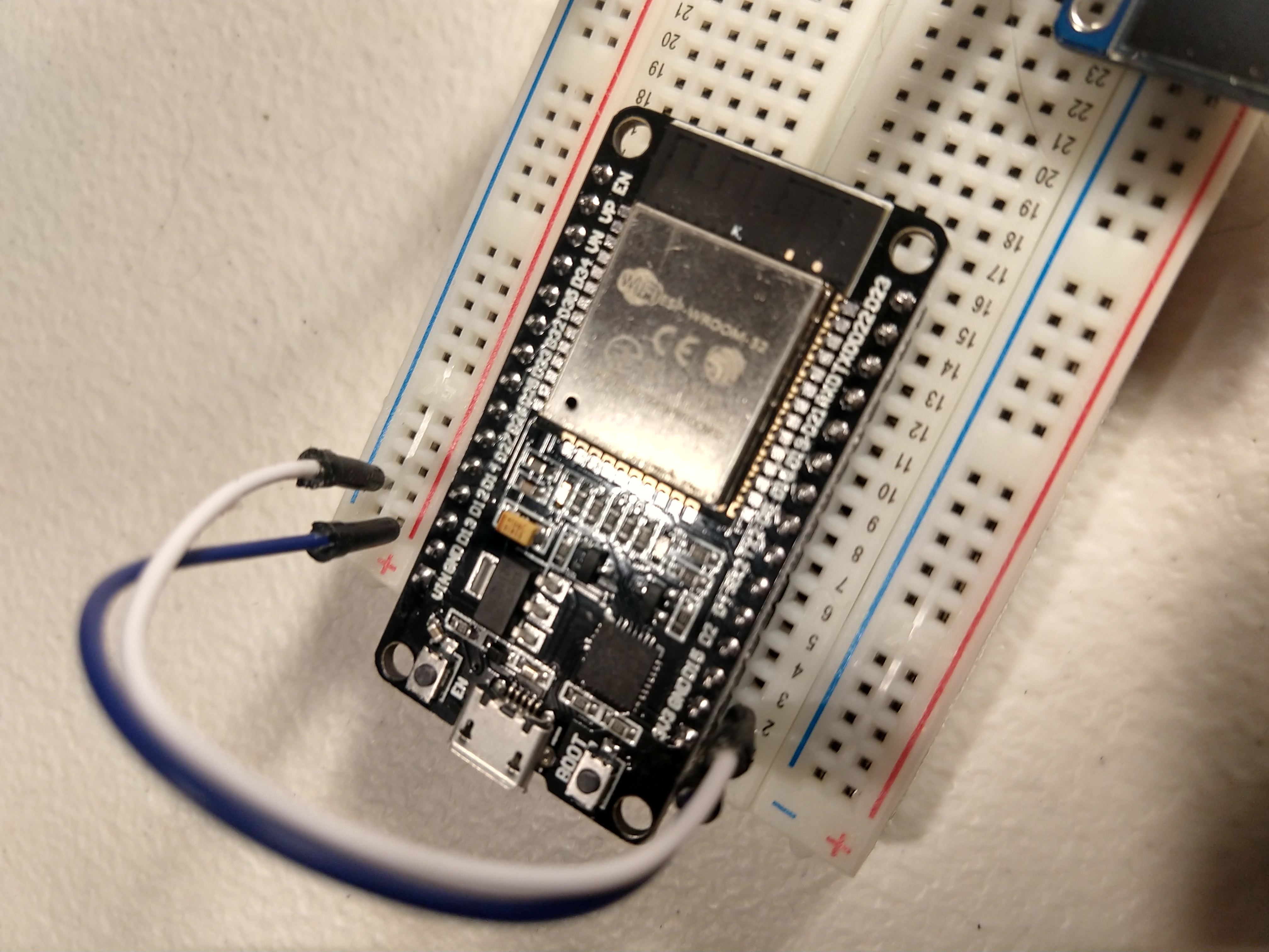
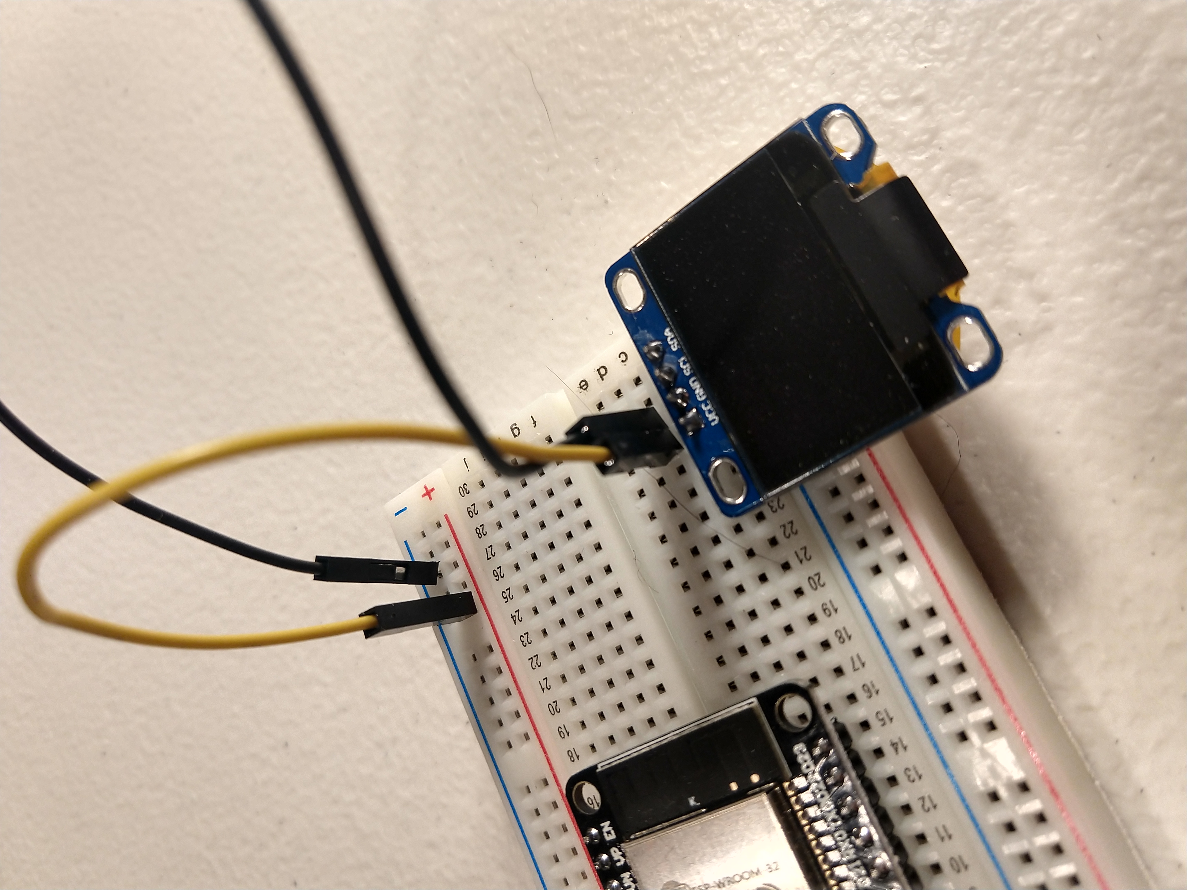
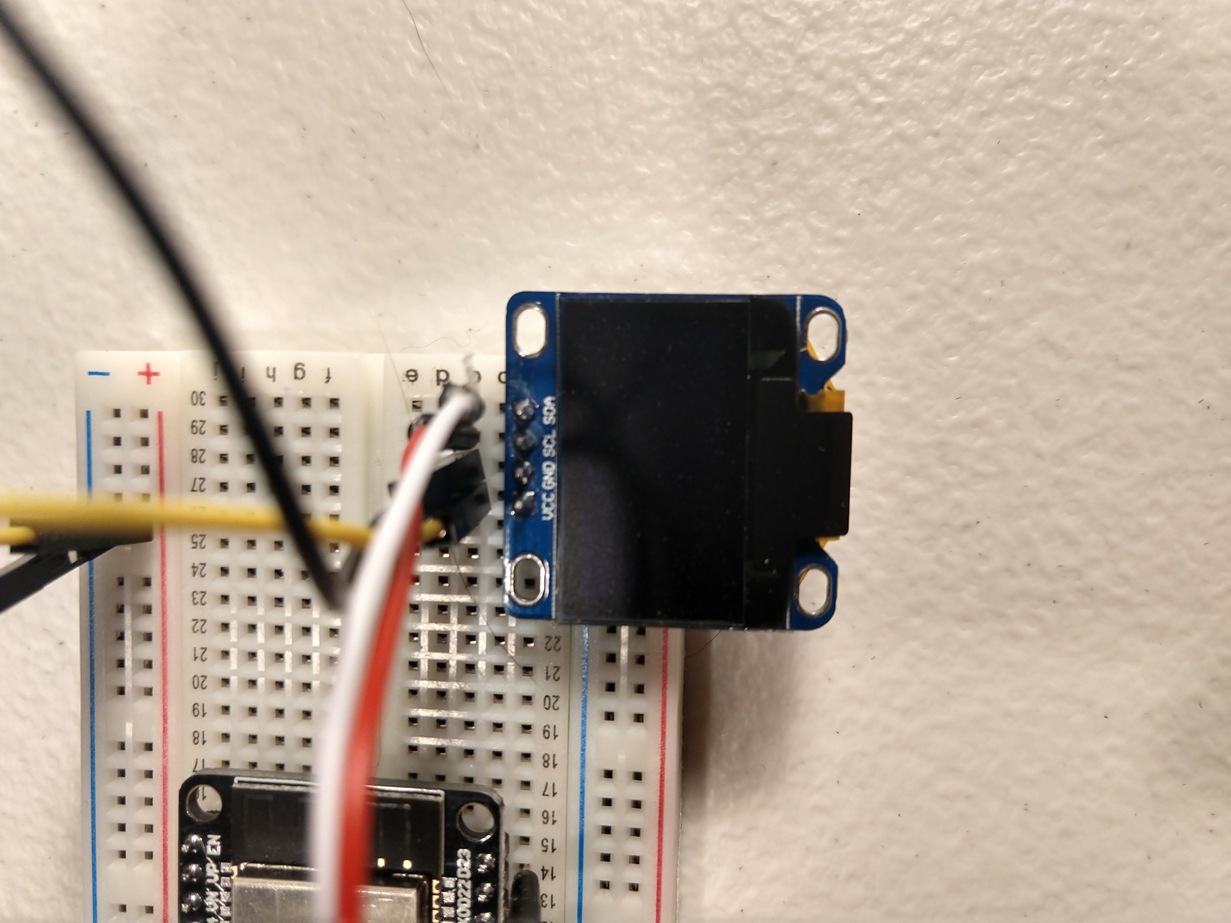
Now that we have our basic Wifi sniffer up and running lets upgrade the way we display our information with an OLED screen. I’ve added a link above to the screen I use, they are cheap and have always worked great for me. I also like to use a mini breadboard to make prototyping this out a little easier, but you can just connect the screen directly if you would like. The first thing we need to do here is connect the power and ground to our OLED screen. The top image below is the pinout diagram for the ESP32 I’m using. In the image we can see the bottom right two pins are marked ‘GND’ and ‘3V3’. This is our ground(labeled GND) and 3.3 volt power source(labeled 3V3). As seen in the bottom left picture, you are going to want to hook the power source up to the positive rail on the breadboard and the ground up to the negative rail. Once our top two rails on our breadboard have power flowing through them, it’s time to flow it to the OLED screen. In the bottom right image you can see that two of the pins on the OLED screen are labeled ‘VCC’ and ‘GND’. We want to take jumper cables and connect the ‘VCC’ pin to our 3.3 volt positive rail and the ‘GND’ pin to our negative ground rail.
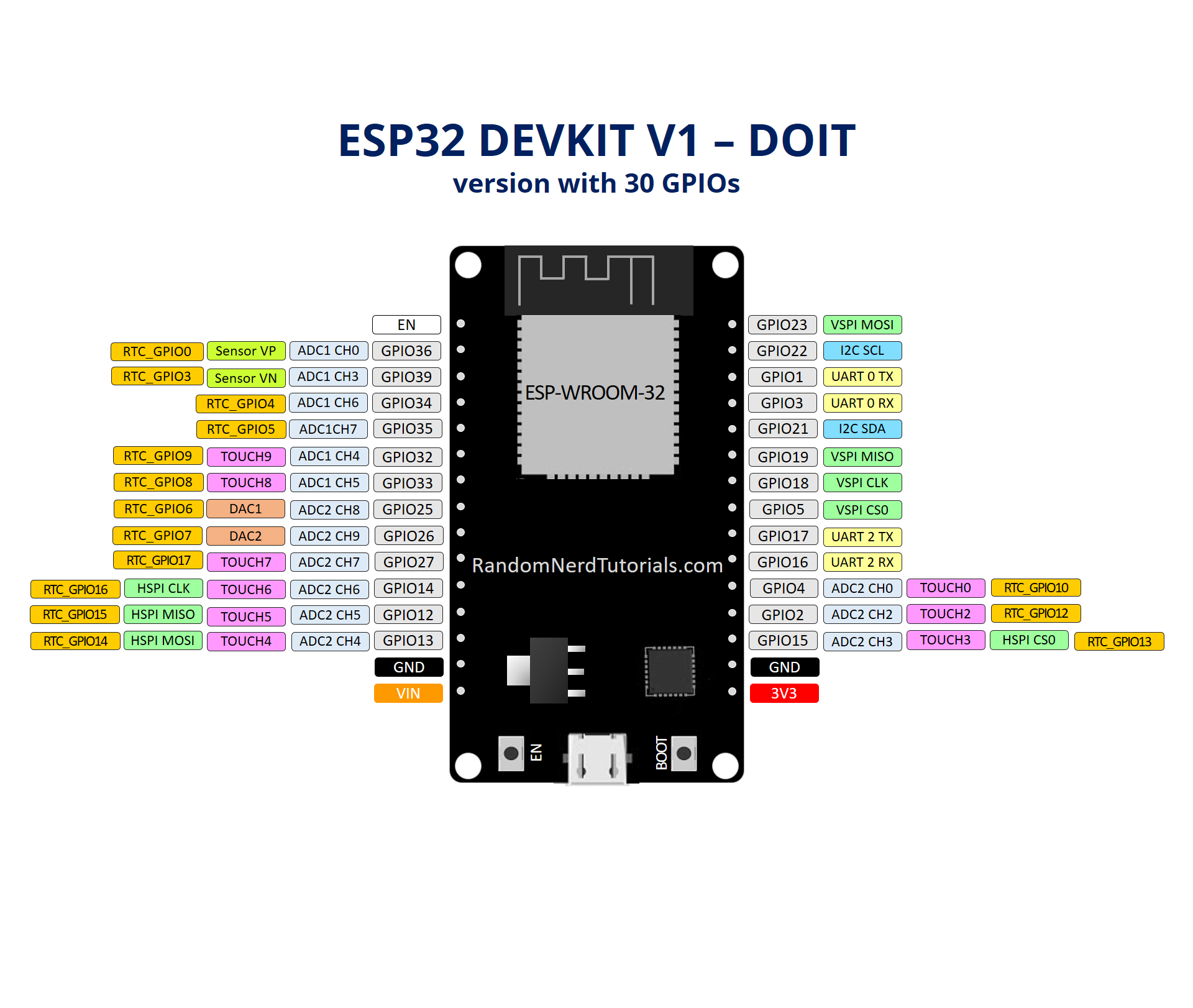
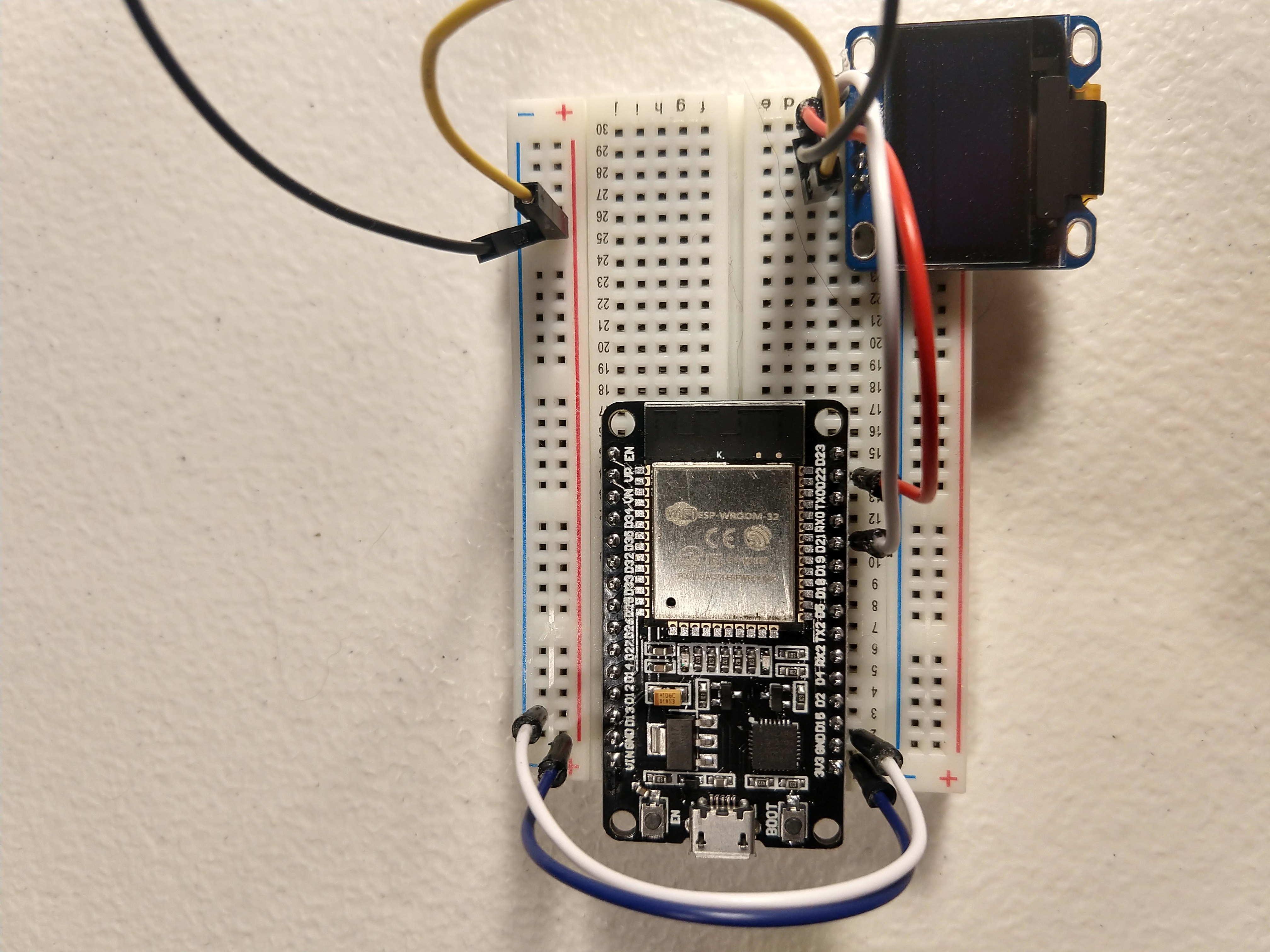
Now that we have power running to the OLED screen, it’s time to hook up the two data pins labeled ‘SCL’ and ‘SDA’. We are going to hook the ‘SDA’ pin on the screen to the pin on the ESP32 labeled ‘GPIO21’ on the top image above. Next we want to connect the ‘SCL’ pin on the screen to the pin labeled ‘GPIO22’ on the ESP32. Once you are all done your setup should look like the two images below.
Testing Our OLED Screen
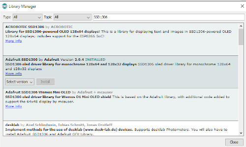
Now that our screen is wired up, we need to use some sample code to test it out and make sure everything is working. First, we need to make sure we have the library installed to facilitate communication with the screen. Open up your Arduino IDE and navigate to the Sketch Menu->Include library->Manage Libraries. Alternately, you can use the hotkey ctrl+shift+I. This will open up the window below. Once we have the manage libraries screen open, we can use the search bar on the right side of the screen to search for ‘SSD1306’, the driver for the screen we are using. After searching, you should see ‘Adafruit SSD1306’. Highlight this option and click the install button that appears.
Once the install finishes, we are ready to test our screen out. Now you should be able to use the menu on the top of the screen to open the following example file: File->Examples->Adafruit SSD1306->ssd1306_128x64_i2c. This will open up the test example code. We need to modify this slightly to get our screen working. First, we need to change the line below from a value of 4 to a value of -1. You should change it from the top line in the snippet below to the bottom line. We do this because we are sharing the Arduino reset pin on our setup.
// It will look like this
#define OLED_RESET     4

// Change it to this
#define OLED_RESET    -1
The last thing I needed to do in order to get my OLED screen working is changing the i2c address set in the code. The example code passes ‘0x3D’ as the default i2c address, as seen in the code block below. On my ESP32 that was not the correct address. Luckily for us, Random Nerd Tutorials created an i2c address scanner that we can find here. All you have to do is upload that code to your ESP32 and open up the serial monitor in Arduino IDE (Ctrl+Shift+M). You may also need to change the baud rate in the bottom right of the serial monitor. I had to set mine to 115200 or it just printed gibberish. This code will log out your i2c address in the serial monitor, in my case it was logging out ‘0x3C’. I updated the ‘0x3D’ in the code below to ‘0x3C’, uploaded the modified example script to my ESP32 and boom, we have stars and boxes printing on our OLED screen.
if(!display.begin(SSD1306_SWITCHCAPVCC, 0x3D)) {
    Serial.println(F("SSD1306 allocation failed"));
    for(;;);
}
Creating A WiFi Scanner
Now that we have our screen working and our ESP32 grabbing MAC addresses out of the air, let’s put it all together and display a list of MAC addresses seen on our screen. The first challenge we are going to run into here is the size of the screen. When in promiscuous mode, there is a good chance that you’ll have a lot of WiFi traffic going on around you and you can only display about 5 MAC addresses on the screen at a time. In the next article we’ll crafting a slightly better solution and dropping inactive MAC addresses off the list, but for now we are just going to paginate the list of MAC addresses on our screen. Having the device change pages every few seconds and showing a complete list of all MACs it has seen. Below I have added the updated code, it takes the MACs collected in the previous steps and prints them to the display. The first new function you will see is ‘setupDisplay’. This function turns on the display, sets the text color and size that we want to use. We also added a call to another new function called ‘displayFoundMac’. This function resets and clears the screen, it then displays the MACs for the current page. We also added some code to the ‘loop’ function to change the current page and display the new page every 2000 milliseconds.
#include "esp_wifi.h"
#include <vector>
#include <SPI.h>
#include <Wire.h>
#include <Adafruit_GFX.h>
#include <Adafruit_SSD1306.h>

using namespace std;

#define maxCh 11
#define MAX_MACS_ON_SCREEN 5
#define OLED_RESET -1
#define SCREEN_WIDTH 128
#define SCREEN_HEIGHT 64

Adafruit_SSD1306 display(SCREEN_WIDTH, SCREEN_HEIGHT, &Wire, OLED_RESET);

int curChannel = 1;
int currentPage = 1;
long lastPageChange = 0;
vector<String> macArray;

const wifi_promiscuous_filter_t filt = {
    .filter_mask=WIFI_PROMIS_FILTER_MASK_MGMT|WIFI_PROMIS_FILTER_MASK_DATA
};

typedef struct {
    uint8_t mac[6];
} __attribute__((packed)) MacAddr;

typedef struct {
  int16_t fctl;
  int16_t duration;
  MacAddr da;
  MacAddr sa;
  MacAddr bssid;
  int16_t seqctl;
  unsigned char payload[];
} __attribute__((packed)) WifiMgmtHdr;

void sniffer(void* buf, wifi_promiscuous_pkt_type_t type) {
    wifi_promiscuous_pkt_t *p = (wifi_promiscuous_pkt_t*)buf;
    WifiMgmtHdr *wh = (WifiMgmtHdr*)p->payload;

    MacAddr mac_add = (MacAddr)wh->sa;
    String macAttack;
    for (int i = 0; i < sizeof(mac_add.mac); i++) {
        String macDigit = String(mac_add.mac[i], HEX);
        if (macDigit.length() == 1) {
            macDigit = "0" + macDigit;
        }

        macAttack += macDigit;
        if (i != sizeof(mac_add.mac) - 1) {
          macAttack += ":";
        }
    }

    macAttack.toUpperCase();

    // Prevent duplicates
    for (int i = 0; i < macArray.size(); i++) {
        if (macAttack == macArray[i]) {
            return;
        }
    }

    macArray.push_back(macAttack);
}

int getMaxPages() {
    int maxPages = macArray.size() / MAX_MACS_ON_SCREEN;
    if (macArray.size() % MAX_MACS_ON_SCREEN > 0) {
        maxPages++;
    }
    return maxPages;
}

void setWifiPromiscuousMode() {
    wifi_init_config_t cfg = WIFI_INIT_CONFIG_DEFAULT();
    esp_wifi_init(&cfg);
    esp_wifi_set_storage(WIFI_STORAGE_RAM);
    esp_wifi_set_mode(WIFI_MODE_NULL);
    esp_wifi_start();
    esp_wifi_set_promiscuous(true);
    esp_wifi_set_promiscuous_filter(&filt);
    esp_wifi_set_promiscuous_rx_cb(&sniffer);
    esp_wifi_set_channel(curChannel, WIFI_SECOND_CHAN_NONE);
}

void setupDisplay() {
    if(!display.begin(SSD1306_SWITCHCAPVCC, 0x3C)) {
        Serial.println(F("SSD1306 allocation failed"));
        for(;;);
    }

    display.setTextSize(1);
    display.setTextColor(WHITE);
}

void setup() {
    Serial.begin(115200);

    setWifiPromiscuousMode();
    setupDisplay();
}

void changeWifiChannel() {
    if(curChannel > maxCh){
        curChannel = 1;
    }

    esp_wifi_set_channel(curChannel, WIFI_SECOND_CHAN_NONE);
    delay(1000);
    curChannel++;
}

void displayFoundMac() {
    display.setTextSize(1);
    display.setTextColor(WHITE);

    delay(2000);
    display.clearDisplay();

    display.setCursor(0, 6);
    display.println("Active Clients");

    display.setCursor(90, 6);
    display.println(String(currentPage) + "/" + String(getMaxPages()));

    int row = 0;
    int startIndex = (currentPage - 1) * MAX_MACS_ON_SCREEN;
    int endIndex = startIndex + MAX_MACS_ON_SCREEN;
    for (int i = startIndex; i < endIndex; i++) {
        if (i < macArray.size()) {
            display.setCursor(0, (row * 9) + 16);
            display.println(macArray[i]);
            row++;
        }
    }
    display.display();
}

void loop() {
    changeWifiChannel();

    if (lastPageChange == 0 || (millis() - lastPageChange > 2000)) {
        lastPageChange = millis();

        if (macArray.size() <= MAX_MACS_ON_SCREEN) {
            displayFoundMac();
            return;
        }

        if (currentPage == getMaxPages()) {
            currentPage = 1;
        } else {
            currentPage++;
        }

        displayFoundMac();
    }
}
Wrapping Up
We’ve covered a lot of ground in this article and I think now is a good time to break. In the next article we are going to add buttons to allow us to navigate the display, as well as improving our code to drop off MACs it hasn’t seen in a few minutes. Eventually we will work up to building a deauth device, going over how deauth attacks work and why we can do them without any authentication. If you have any questions or need any help getting your ESP32 setup, don’t hesitate to reach out via email or Twitter. As always, thank you for reading and happy hacking!